
How to Crimp a Cold-Press Terminal: The Five-Step Method That Actually Works
First the conclusion: whether a crimp terminal works is about 90% determined by the crimp itself, not by the terminal. From the same batch of terminals, one operator produces joints that last 30 years, another produces joints that blacken and burn the cable within three months. Same material, same specification, wildly different results.
I have seen this on site far too often: a worker picks up a pair of ordinary pliers, drops the terminal over the wire, squeezes until it “feels” tight, and calls it done. It looks convincing, but no cold weld has taken place — the copper strands and the barrel are merely squashed together, with countless gaps still between them. The moment current flows, those gaps start heating.
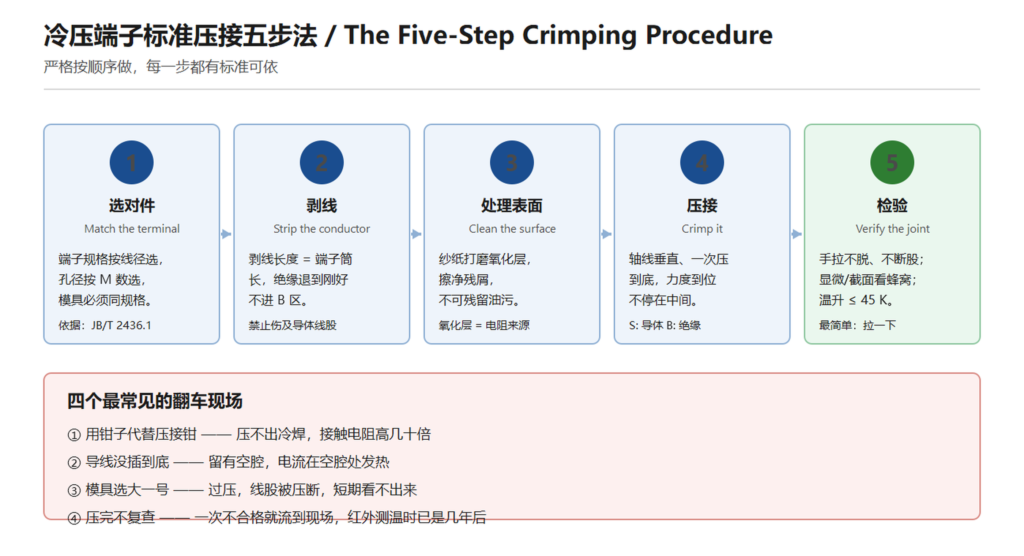
So this article skips the fluff and walks through the five standard steps of a proper crimp. For each one: which standard it comes from, what “done correctly” looks like, and what goes wrong if you skip it. If you just want the short version, the diagram and the five-step table are enough to get going. The rest explains the why.
I. First: what “correctly crimped” actually means
Cold pressing (also called cold welding) can be explained in one sentence: the stranded copper conductor and the metal barrel of the terminal are compressed together until the two metals achieve molecular-level bonding at the contact interface, forming a gas-tight unit.
The key phrase is “molecular level”. Squeezing with pliers is mechanical interference — the surfaces stay rough and full of gaps. Crimping with a matched die forces the two metals into each other’s crystal lattice and squeezes the voids out. The two may look similar in “crimp height”, but the actual conductive area differs by an order of magnitude.
There is a widely used industry criterion: a sound joint must not have a contact resistance greater than 1.1× the resistance of a conductor of the same length. That sounds abstract. In practice it means a good crimp is electrically almost indistinguishable from the wire itself. Anything less than that comes back as temperature rise.
Before the method, one expectation needs setting: crimping is a standardised process, not a craft. JB/T 2436.1, the T/ACCEM group standard, USCAR-21 and VW 60330 all exist precisely because crimp quality has to be measurable, reproducible and judgeable — not judged by a master technician’s feel. “I’ve been doing this for twenty years” carries little weight here. Hands shake, attention wanders, dies wear out.
II. Choosing the right crimping tool
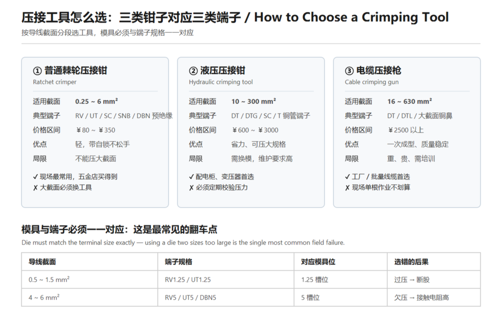
Get the tool wrong and the best technique in the world still fails. Split by conductor cross-section — this is the simplest way to decide:
| Tool | Cross-section | Typical terminals | Price | In one line |
|---|---|---|---|---|
| Ratchet crimper | 0.25 – 6 mm² | RV / UT / SC / SNB / DBN pre-insulated | $12 – $50 | Light, self-locking, the most common site tool |
| Hydraulic crimper | 10 – 300 mm² | DT / DTG / SC / T copper tube terminals | $80 – $400 | Effort-saving, dies interchangeable — the switchgear standard |
| Cable crimping gun | 16 – 630 mm² | DT / DTL / large copper lugs | $350 and up | One-shot forming, consistent quality — factory and batch work |
A few practical notes on buying and using them:
- The ratchet mechanism is the whole point. It stops at the right position automatically, so you cannot over-crimp. The classic beginner’s mistake is squeezing “twice to be sure” with ordinary pliers and crushing the strands.
- Hydraulic tools need periodic pressure calibration. As the pressure decays, the die still closes and the crimp still looks right — but the joint is hollow. This is why T/ACCEM requires the crimping tool to be certified by a professional body.
- Dies are consumables. Worn jaws leave a shallower impression. It looks more compressed than it is, while the actual contact force is lower. A slow, invisible form of sabotage.
- One tool for every job is the most common false economy. Each terminal size needs its own die slot. Do not expect a single crimper to cover everything.
If you are shopping for a tool right now, the shortcut is: up to 6 mm², buy a ratchet crimper; up to 300 mm², buy a hydraulic crimper; beyond that, go straight to a cable crimping gun. The deciding factor is not budget — it is how thick your cable is and how many terminations you have to make.
III. The five-step procedure
Each step below covers what “done correctly” looks like and what happens when you get it wrong.
Step 1: match the parts (get this wrong and everything after it is wasted)
A terminal is not “about the right size”. The barrel bore must match the conductor diameter, the stud hole must match the device stud, and the die slot must match the terminal size. All three, every time.
The classic selection error is reading the wire size as the hole size. You are holding 2.5 mm² and you see “RV5” and assume it means 5 mm² conductor. It does not. In the RV series, the 5 is the stud hole size — M5 — while 2.5 mm² falls in the “2” wire-range band. That is the whole meaning of RV2-5: RV family, wire band 2 (1.5–2.5 mm²), M5 stud hole.
A hole that is too small will not fit. A hole that is too large leaves too little contact area, the screw cannot clamp properly, and the contact resistance climbs immediately. The rule is firm: a hole 0.2–0.5 mm larger than the stud is right.
Step 2: strip the conductor (get the length wrong and the prettiest crimp is worthless)
Strip length equals barrel length. The conductor goes all the way to the bottom and never past the mouth. Strip back the insulation to just past where it needs to enter zone B — it has to grip the insulation for stress relief, but too much and it bottoms out against the barrel wall before the conductor is home.
More important while stripping: do not damage the strands. Use a proper stripper, not a knife. A blade pressed down flattens and severs strands you cannot see, so the conductive area is already reduced, and that break will heat up in service.
One point is routinely overlooked: an insufficient strip length is the sneakiest failure of all. With the conductor only half inserted, the tool still produces a perfectly hexagonal-looking crimp. A laboratory temperature-rise test may even pass. But installed on site and running at full load through a summer, the current finds too few metal contact points in the void at the back of the barrel, and the heat accumulates there.
Step 3: clean the surface (ten seconds that save ten years)
That dull reddish layer on bare copper is copper oxide, and its resistance is far higher than pure copper. Sand it back with fine abrasive or a dedicated copper brush until bright copper shows, wipe it with a lint-free cloth, and leave no oil or metal debris behind.
Ten seconds of work, and it is the first insurance policy on crimp quality. Skip it and the contact resistance can be several times the qualified value — and the deviation is very hard to catch in inspection, because the joint still looks acceptable.
Step 4: crimp (axis perpendicular, one stroke to bottom)
Slide the terminal onto the conductor, keeping the terminal axis perpendicular to the wire axis, place it in the matching die slot, and crimp to the bottom.
Details that matter:
- Crimp once, to bottom. Do not go back for a second squeeze. Re-compressing an area that is already compressed can crack the barrel.
- Do not crimp off-centre. One side over-compressed, the other under-compressed, and it shows immediately on the cross-section.
- Large copper lugs usually need two crimps — first toward the conductor end, then toward the stud end, leaving 2–3 mm between the impressions so the crimping sequence is unambiguous.
- On a hydraulic tool, release only after the audible click. That is the “closed” signal. Do not let go early.
On the two-crimp practice for large lugs: when the conductor and the barrel are under pressure they undergo plastic flow — the material deforms. If everything is compressed in one stroke, the load is uneven and one side can collapse. C crimping in sequence fixes the conductor end first and then compacts the root, which is physically sound. This is exactly the logic the automotive harness industry applies under USCAR-21.
Step 5: verify (one pull tells you more than any document)
Every crimp must be verified. The most effective field check is also the simplest: grip the terminal, twist the cable hard, and pull.
The acceptance criteria:
- No relative movement at all between terminal and conductor;
- The conductor has not backed out of the barrel mouth and no strands have splayed;
- Looking into the mouth, no strands fan out or splay visibly;
- The impressions sit in the right places — zone A on the conductor and zone B on the insulation, not randomly in the transition zone.
Where the setup allows, add two further safeguards:
- Cross-section dissection. Cut a sample open and check whether zone A shows a honeycomb structure. Continuous gaps between strands mean the crimp did not close. This is the final criterion, and the automotive industry does it on 100% of terminals (both USCAR-21 and VW 60330 require it).
- Micro-ohmmeter measurement. A sound crimp reads in the micro-ohm range, essentially the same as a conductor of equal length. If it reads clearly high, cut it off and redo it. Terminals are cheap; burnt cabinets are not.
- Temperature-rise test. With rated current applied and stabilised, GB/T 2314 requires the crimped section to stay within 45 K of ambient. The T/ACCEM standard for general cold-pressed connection terminals is tighter, at 30 K. Use the right number for the right standard — do not mix them.
IV. Reading a crimp cross-section: three zones and a set of geometric parameters
No standard will tell you what a good crimp looks like, but they do divide the cross-section into functional zones, each with its own criterion. The VW 60330 three-zone split is the international language here:
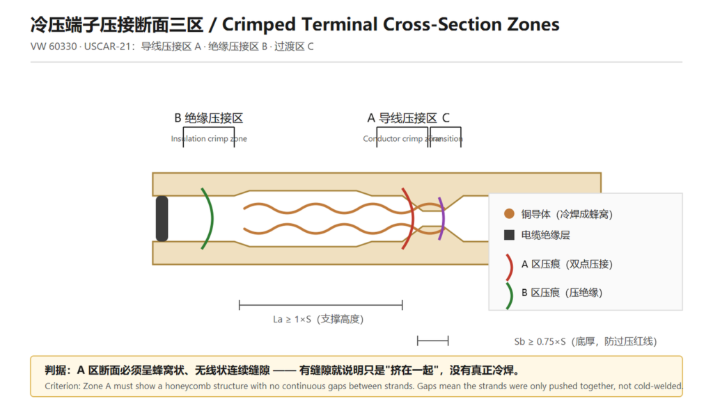
Here is how the three zones divide the work:
| Zone | Name | Function | Criterion |
|---|---|---|---|
| Zone A | Conductor crimp zone | Gas-tight cold weld between strands and terminal | Honeycomb structure, no continuous gaps between strands |
| Zone B | Insulation crimp zone | Grips the insulation, diverts pull away from zone A | Insulation is reliably held and does not slip |
| Zone C | Transition zone | Observes whether material flow is reasonable | No cracks, no abnormal stress concentration |
“Honeycomb” is the key word of the whole inspection. If you can still see clear continuous gaps between the strands on the cut face, they were merely pushed together and no cold weld happened. Gas-tight means not even a gas molecule can pass — and only then do oxidation and corrosion have nowhere to begin.
Beyond the zoning, the standards give a set of geometric parameters. These are the pass lines for a crimp cross-section:
| Parameter | Symbol | Pass criterion | Meaning |
|---|---|---|---|
| Support angle | αw | ≤ 30° (deviation from vertical) | Whether the crimp wings effectively enclose the conductor |
| Support height | La | ≥ 1×S (S = terminal material thickness) | Whether the crimp wing ends support each other |
| Crimp wing end gap | Fa | ≥ 0.1×S | The wing ends must not touch the inner barrel wall |
| Burr height | Fh | ≤ 1×S | Die wear and clearance control |
| Base thickness | Sb | ≥ 0.75×S | The first red line against over-compression |
| Compression ratio | — | approx. 10–20% (VW / USCAR) | Densification of the copper strands |
Sb ≥ 0.75×S deserves a paragraph of its own. It is the prerequisite indicator for judging over-compression: if the base of the terminal has been squeezed too thin, the applied force exceeded what the material can reasonably withstand, and the strands may already be damaged or even broken. A resistance reading may still look fine in the short term, but strand fracture in a vibration environment is only a matter of time.
V. The four ways site work goes wrong
Finally, here are the four classic failures, laid out so you can check your own practice against them:
| What goes wrong | Why it is wrong | Consequence | Correct practice |
|---|---|---|---|
| Pliers used instead of a crimper | Insufficient pressure — no cold weld | Contact resistance tens of times too high; heats as soon as it carries current | Dedicated crimper with matching die |
| Conductor not inserted fully | Void at the bottom of the barrel, too few contact points | Heat builds in the void; only visible on an infrared scan | Strip length equals barrel length, insert to the bottom |
| Die one size too large | Over-compression crushes the strands | Looks fine short term; strands break under vibration and contact deteriorates | Die size matched to the terminal, strictly |
| No verification after crimping | Non-conforming parts reach site | Problem surfaces years later, when diagnosis costs the most | Pull test on every batch; cross-section on critical circuits |
The first three are “you were not careful at the moment”. The fourth is “nobody asked you to check”. And the fourth is by far the most dangerous — because the first three can all be caught by one pull test. If the process contains no verification step, doing it right goes unnoticed and doing it wrong goes unchallenged.
VI. On “how to use” videos: why I trust the written standard more
Searching for a crimp terminal tutorial video returns plenty of demonstrations, and that is a good thing — visual teaching really is the clearest way to learn how to hold the tool and how to seat the terminal.
But video has a structural limitation: it can show you the correct method, but it cannot tell you where your own method is wrong. After watching a video you know you should seat the terminal squarely and push the conductor all the way in — but whether the joint in your hand is over-compressed or under-compressed, the video cannot help with that.
So my advice is: use video to learn the movement, use the standard to judge the result. The movement can be copied from a technician; the pass line has to come from JB/T 2436.1, T/ACCEM, USCAR-21 and VW 60330, the documents with actual numbers in them. Combine the two and you have a complete process.
And the best learning material, in the end, is your own cross-section. Cut one, crimp one, compare whether there are gaps between the strands and whether the impressions landed in the right place. Three sessions of that beats thirty videos.
Wrapping up
Back to where we started: whether a crimp terminal works is about 90% determined by the crimp. The terminal itself only provides material strength and a conductive cross-section; the connection is established by the act of crimping.
The way to keep this simple is to hold five rules: match the parts, strip to the right length, clean to bright copper, crimp perpendicular to the bottom, and pull to check. None of that takes talent or experience — it only takes not cutting corners. Do it, and your joint is electrically almost indistinguishable from the wire itself. Skip it, and the finest terminal in the world is just a lump of metal waiting to heat up.
And for anyone still wondering whether a crimp terminal is necessary at all — why not just tighten a screw? The answer depends heavily on the scenario, and that is the subject of the next article.