
Crimp Terminal Model Codes Explained: RV, UT, DBN and OT Decoded
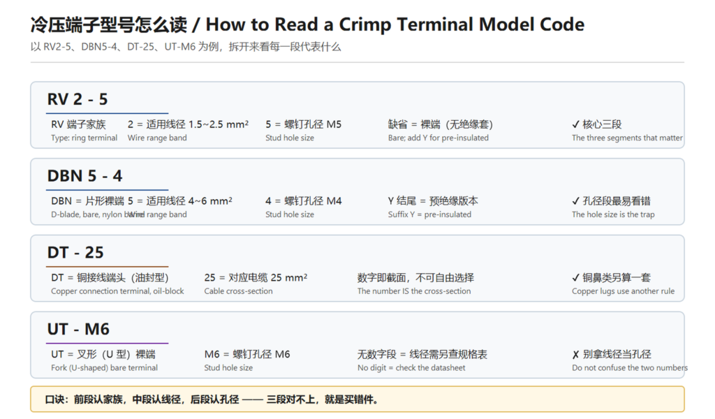
This is the core selection table. When you write “RV2-5” on a purchase order, purchasing pairs it with 2.5 mm² wire and an M5 hole, and what arrives is correct. But if you write “RV5”, people may read it as 5 mm² wire with a 5 mm hole — whereas in RV5 the 5 is the hole size, and the wire band is the 4–6 mm² range. Best practice is to write the specification alongside the code: “RV2-5 (1.5–2.5 mm², M5 hole)”. That alone eliminates a lot of back-and-forth email.
III. What the suffixes mean
Model codes often carry trailing characters. They are just as defined as the rest:
| Suffix | Meaning | Example | Why it matters |
|---|---|---|---|
| Y | Pre-insulated version with a nylon sleeve | RV5-4Y | Protection when working live; slightly higher price |
| D5-4 | Combined spec: 5 = 4–6 mm², 4 = M4 hole | DBN5-4 | Defines both wire range and hole in one code |
| 90D | 90° angle / entry direction identifier | RNB-90D5-4 | Sets the wire entry direction and assembly space |
| E | DT series small-head (economy) version | DT(E)-25 | Structurally different from the standard large-head DT |
| None | Bare terminal, no sleeve | RV2-5 | You must insulate it yourself |
One warning in particular: DT versus DT(E). DT is the standard large-head type, DTG is the tube version with an open tail and no oil blocking, and DT(E) is the small-head economy type. All three look alike, and none of them is interchangeable. For transformer outgoing terminals and oil-immersed equipment, only the oil-block DT will do.
IV. The OT open barrel terminal, in detail
OT is searched for more than any other single model, so it deserves its own section.
OT stands for Open Barrel Terminal — the open barrel (also written as O-type or A-type) terminal. Its structure differs from a crimp terminal in kind:
- It is a copper part, not a thin-wall stamped tube. OT terminals are formed from copper tube or bar, and the wall is far thicker than on an RV-class terminal.
- It is open. That is where the name comes from — you can see whether the conductor is fully seated during crimping, and verify the result afterwards. SC (inspection-hole) also has a viewing hole, but it is a different construction.
- It carries far more current. Common sizes run from 10 mm² up to 630 mm² — the workhorse of switchgear main circuits and transformer incomers.
- Its number IS the cable cross-section. OT-25 is 25 mm², with no separate wire-band and hole segments. The stud hole size must be confirmed separately.
A few OT variants you will meet during selection:
| Model | Name | Structure | Typical use |
|---|---|---|---|
| OT | Open barrel terminal | Open; crimping visible | Switchgear main circuits, general cabling |
| OTG | Dual-hole open barrel | Two stud holes, easy to parallel | Parallel busbars, multi-core cables |
| OTA | Type A terminal | Open; broader size range | Common overseas naming convention |
| OTB | Type B terminal | Open; threaded hole type | Standardised parts |
| DT | Copper connection terminal | Closed tail (oil-block) | Transformer outgoing, oil-immersed equipment |
| SC | Inspection-hole terminal | Viewing hole in the tube wall | Sites where the crimp must be visually verified |
How do you choose between OT and DT? One line: OT for ordinary switchgear main circuits; DT (with the oil-block tail) for transformer outgoing terminals, oil-immersed equipment, and anywhere moisture or oil must be kept out of the barrel. Visually, the DT tail is closed and the OT tail is open.
V. Copper terminal quick reference, 10 to 240 mm²
The table below lines up the most common copper sizes with their reference ampacity, so you can check a part against the one in your hand:
| Cable (mm²) | OT open | DT oil-block | SC inspection | DTG tube | Ref. ampacity (A) | Common stud hole |
|---|---|---|---|---|---|---|
| 10 | OT-10 | DT-10 | SC10 | DTG-10 | 50 – 80 | M6 / M8 |
| 16 | OT-16 | DT-16 | SC16 | DTG-16 | 60 – 106 | M6 / M8 |
| 25 | OT-25 | DT-25 | SC25 | DTG-25 | 80 – 143 | M8 / M10 |
| 35 | OT-35 | DT-35 | SC35 | DTG-35 | 100 – 175 | M8 / M10 |
| 50 | OT-50 | DT-50 | SC50 | DTG-50 | 125 – 223 | M10 / M12 |
| 70 | OT-70 | DT-70 | — | DTG-70 | 160 – 265 | M10 / M12 |
| 95 | OT-95 | DT-95 | — | DTG-95 | 180 – 329 | M12 / M16 |
| 120 | OT-120 | DT-120 | — | — | 250 – 382 | M12 / M16 |
| 150 | OT-150 | DT-150 | — | — | ~ 445 | M12 / M16 |
| 185 | OT-185 | DT-185 | — | — | 315 – 519 | M16 |
| 240 | OT-240 | DT-240 | — | — | 400 – 609 | M16 / M20 |
Ampacity figures are reference values drawn from several sources; allow 15–20% margin in real service. Confirm the stud hole against the actual equipment — hole sizes can differ between manufacturers on the same model code.
VI. Small-section quick reference (RV / UT / DBN)
Control cabinets and terminal blocks use this family. The table is arranged by hole size, so you can match it against the stud you actually have to terminate:
| Wire band | Wire range | M3 | M4 | M5 | M6 | M8 | M10 |
|---|---|---|---|---|---|---|---|
| 1 / 1.25 | 0.25 – 1.5 mm² | — | RV1.25-4 / UT1.25-4 | — | — | — | — |
| 2 | 1.5 – 2.5 mm² | — | RV2-4 / UT2-4 / DBN2-4 | RV2-5 / UT2-5 | RV2-6 | — | — |
| 5 | 4 – 6 mm² | — | RV5-4 / UT5-4 / DBN5-4 | RV5-5 / UT5-5 | RV5-6 | RV5-8 | RV5-10 |
| 8 / 10 | 10 – 16 mm² | — | — | — | RV6-6 | RV8-8 | RV10-10 |
A trailing Y indicates the pre-insulated version, e.g. RV5-4Y. The nylon sleeve makes it harder to touch a live end while working, at the cost of a slightly higher price and a lower tolerance for crimping temperature.
VII. The three traps in terminal selection
Trap one: reading the wire band as the hole size. This is by far the most common error. RV5-4 means “wire band 5 (4–6 mm²) with an M4 hole” — it is not an alternative way of writing “5 mm hole for 4 mm² wire”. When you see digits in a model code, work out which segment each one belongs to first.
Trap two: assuming one code covers everything. Within the RV, UT and DBN families, the wall thickness, crimp height and die slot of an RV are not interchangeable with those of a UT at the same wire band. Crimping an RV in a UT die produces a different impression position and a different crimp height, even though the wire band is the same. The error does not show up immediately, and long-term reliability quietly degrades.
Trap three: picking the hole “close enough”. Too small and the terminal tears when you force it on. More than a millimetre too large and the screw cannot clamp, so the contact resistance climbs at once. A hole 0.2–0.5 mm larger than the stud is right.
Wrapping up
A model code is not a label — it is a specification. Memorise the three rules (family, wire band, hole size), print the two quick-reference tables above and put them at the workstation, and terminal selection stops being something you need to ask anyone about.
One practical habit that saves real time: never write only the model code on a purchase order. Write “RV2-5, 1.5–2.5 mm², M5 hole, bare” or “OT-25, 25 mm², M10 hole” and put all three parameters on the line. That alone removes at least one round of confirmation emails. It is not fussiness — it is moving the acceptance criteria from the standard straight onto the order.
Once you have the right part, the next step is the crimp itself. The full procedure and the standards behind it are covered in How to Crimp a Cold-Press Terminal: The Five-Step Method.